
Symmetrization of 1ph and 3ph appliances
5.10.2002In many industrial applications there are very large electrical devices connected to the electrical distribution system. These devices should be symmetrical, because the power transmission causes the lowest active losses in this case. Hence, we perform so-called symmetrization of power appliances. Our goal is to create a complex that will strain all phases uniformly. Not to increase present real power is obvious demand by symmetrization process. This, as we will see it later, can be done by using a suitable combination of capacitors or inductors that we connect between individual phases of our device. Symmetrization can be applied not only to existing 3ph devices, but also to 1ph devices that must be fed by 3 phases in practice. It is used mainly for feeding power devices of over 500 kW.
First, we start first with real admittance, for example G = 5 S:
 |
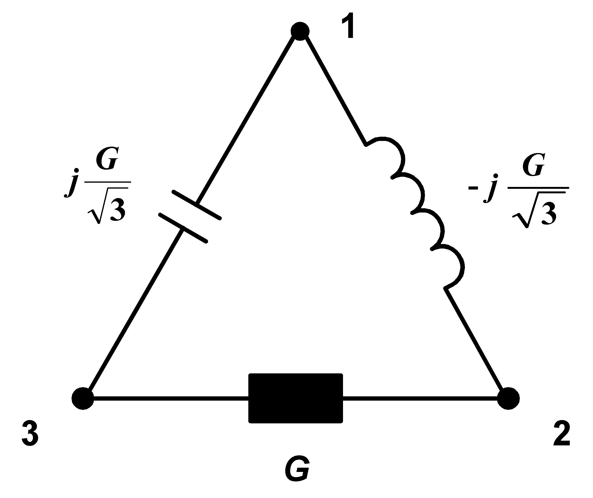
From this admittance we make symmetrical 3ph real load this way:
 |
Derivation:
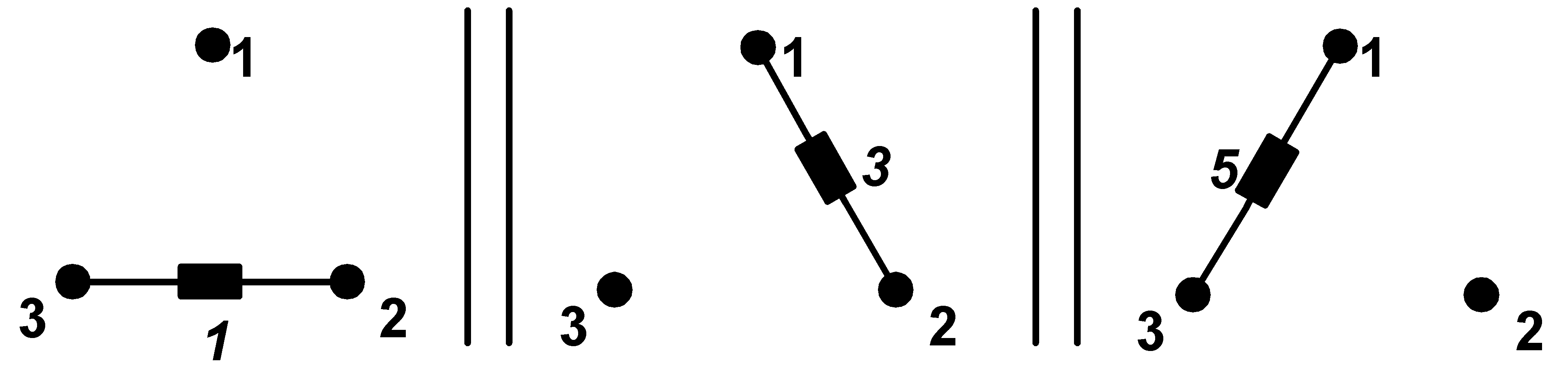
Let we consider connection, labeling and circuit quantity orientation of the circuit elements according to the following scheme:
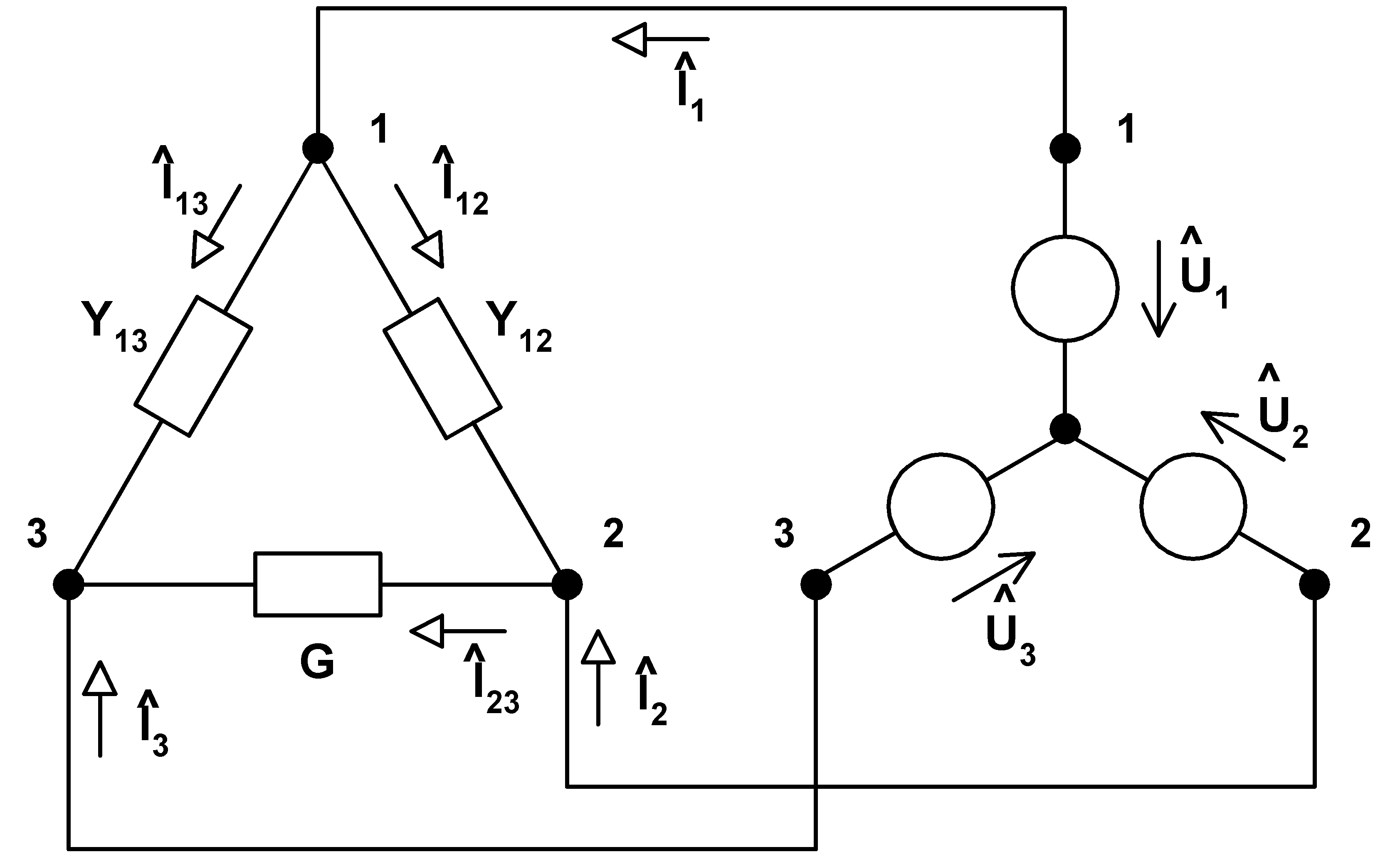 |
Let real load is connected between nodes 2 and 3 with conductivity of G (S). We require load to be real and symmetrical after connection of admittances
Y12 (S) and Y13 (S) real power (picked by the load) has to stay without any changes is the next demand. We translate these requirements to the mathematical language:
# conservation of the real power: Y12 and Y13 are purely imaginary,
# resulting circuit picks no reactive power: Y12 = -Y13; let lay down Y12 = j.Y, Y13 = -j.Y,
# symmetry of picked currents: I1 = k.U1, I2 = k.U2, I3 = k.U3.
Let we establish labeling of the phases voltage by usual form in the energetics:
U1 = U, U2 = U.a2, U3 =
U.a, where  is the operator of rotation in complex plane of
  anticlockwise.
We take advantage by lying down
anticlockwise.
We take advantage by lying down  , although it isn't necessary for the solution. It means only the choice of the beginning of time measuring at passing from phasors to time area. With these conditions holds:
I1 = I12 + I13 = j.Y.(U1 -
U2) - j.Y.(U1 - U3) = j.Y.U.(1 -
a2) - j.Y.U.(1 - a) = k.U1 = k.U
I2 = I23 - I12 = G.(U2 -
U3) - j.Y.(U1 - U2) = G.U.(a2
- a) - j.Y.U.(1 - a) = k.U2 = k.U.a2
I3 = -I23 - I13 = -G.(U2 -
U3) - (-j.Y).(U1 - U3) =
-G.U.(a2 - a) + j.Y.U.(1 - a) = k.U3 =
k.U.a
U, a, G are ordered quantities, Y, k are unknowns. Thus we have 3 equations for 2 unknowns, but equations are linearly dependent: the sum of the left sides is zero at first sight and for the sum of the right sides holds:
k.U.(1 + a2 + a) = 0, because holds 1 + a2 + a = 0.
Solution of the system is in notebooku ,
form; the result is: k = G a Y = -G /
,
form; the result is: k = G a Y = -G / .
.
As we can see, the problem is solved: currents are G -multiplied of the appropriated phases voltage and in addition - according to the presumption - . General real power is:
P = Re{U.G.U} + Re{a2.U. (a2.U.G)* } = U2
.G.(1 + a2.(a2)* + a.a*) = U2.G.(1 + |a2|2 + |a|2) = U2.G.(1 + |a|4 + |a|2) = U2.G.(1 + 1 + 1) = 3.U2.G
Real power of original circuit was without any additional devices: P = G.(.U)2 = 3.U2.G.
Derivation closed.
The point is to connect ideal capacity with an admittance of
5 / S (Siemens) between nodes 1-3 and ideal inductance with an admittance of 5 / S,
between nodes 1-2, so that we receive 3ph symmetrical appliance from original 1ph appliance.
Now let us look at common 3ph unsymmetrical load. By analogical procedure we make this load symmetric (as in the case above). We will apply the same symmetrization procedure for each branch separately. We use the fact that parallel connection of 3ph symmetric real loads behave as one 3ph symmetric real load. In addition, labeling of the phases by numbers 1,2,3 is arbitrary in the course of phase sequence. Thus we can in the course of thought renumber of the phase progress with every load between 2 phases accordingly as before. It can be best demonstrated on a simple example:
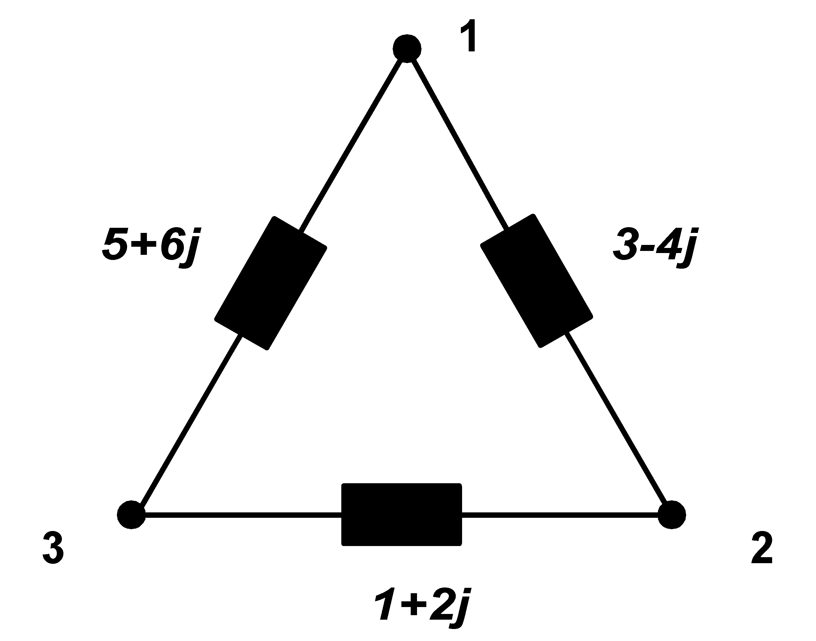 |
First real load will be achieved between single nodes, i.e. we assume admittance 4j S between nodes 1 and 2, admittance -2j S between nodes 2 and 3 and admittance -6j S between nodes 3 and 1. We write down all to the table, transparently.
| branch 1-2 | branch 2-3 | branch 3-1 | |
|---|---|---|---|
| 4j | -2j | -6j | compensed |
The circuit is compensed now, but not yet symmetrized:
 |
Next, we will consider the compensed circuit as a parallel combination of three simple 1ph appliances (but they are every time between 2 different nodes)
 |
and with these separated simple admittances we perform symmetrization, as in the beginning, each admittance separately. If we perform symmetrization of appliance between nodes 1-2, there will be capacity with admittance of 3/
between nodes 2-3 and inductance with admittance of 3/ between nodes 3-1.
We use analogical procedure for symmetrization of the appliance between nodes 3-1. In short, the scheme is rotated always in order to overlay admittance G with required admittance from parallel combination, which is symmetrized right now and we calculate the other branches according to the scheme. Rotating causes no changing of phase sequence. Let us continue in our table:
| branch 1-2 | branch 2-3 | branch 3-1 | |
|---|---|---|---|
| 4j | -2j | -6j | compensed |
| -1j/ | 1j/ | benefits of branches from the scheme | |
| 3j/ | -3j/ | benefits of branches from the scheme | |
| 5j / | -5j/ | benefits of branches from the scheme | |
| ---- | ---- | ---- | ---- |
| j (4 +4/) | j (-2 -2/) | j (-6 +2/) | sum of columns |
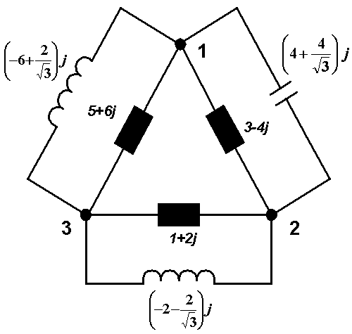
The last row in the table is important for us. This row is a sum of all benefits from each branch. These values determine the type of the element and its quantity. We will connect these elements in parallel to the appropriate branch. It is always possible to replace parallel combination of capacitor and inductor with the one element, inductor or capacitor, according to the final sign of admittance number, because we think the circuit with one voltage frequency and current frequency. Notice that the size of admittance is a function of frequency. Therefore, this replacement is not possible for common circuit with common power supply. For instance, we connect capacitor with the admittance of j(4 +4/) S to the branch between nodes 3-1 (capacitor, because the expression is positive). The resulting scheme is:
 |
Symmetrization is done. Only real power is drawn from the electrical distribution system by this symmetrized appliance. Thus, we can create symmetric load from an arbitrary admittance. However, in practice there is usually no explicit expression of admittance. Often, the way of setting example is as follows:
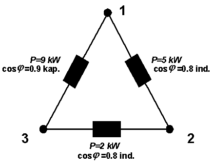 |
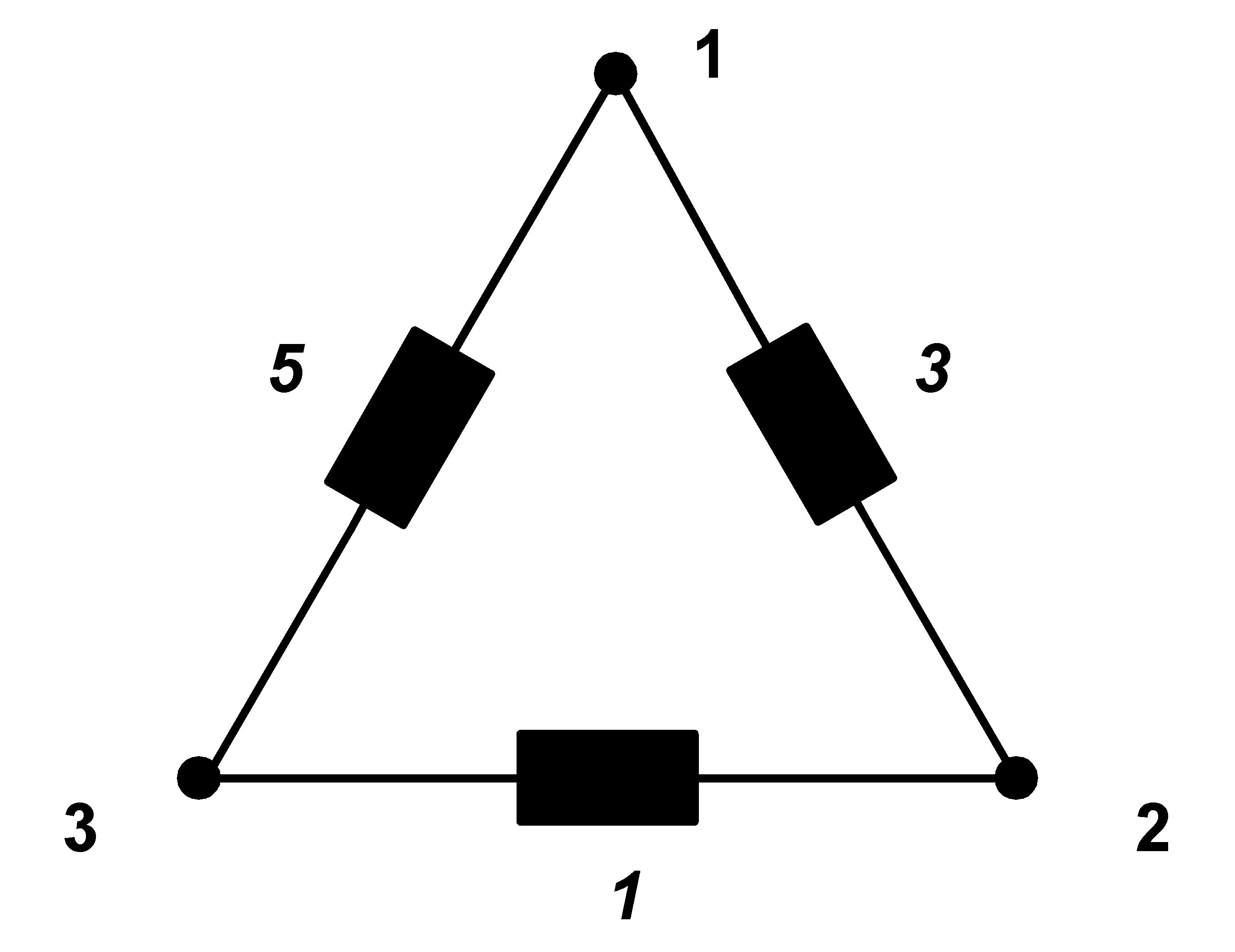
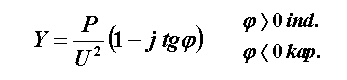
We use the following figure to obtain an explicit expression of admittance. For illustration, the calculation is performed here as well.
 |
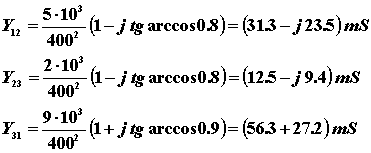 |
We got the explicit expression of admittance. These values are treated as in the previous example.
THE END.